Home
/ 555 Timer Schematic, 555 timer basics | 555 timer application notes, The threshold voltage for the first ic 555, which is determined by the control voltage (modulating signal), is changed to utl (upper threshold level) and is given by.
555 Timer Schematic, 555 timer basics | 555 timer application notes, The threshold voltage for the first ic 555, which is determined by the control voltage (modulating signal), is changed to utl (upper threshold level) and is given by.
555 Timer Schematic, 555 timer basics | 555 timer application notes, The threshold voltage for the first ic 555, which is determined by the control voltage (modulating signal), is changed to utl (upper threshold level) and is given by.. In more simple words, 555 timer is a monolithic timing circuit, which can produce accurate timing pulses with 50% or 100% duty cycle. Between the positive supply voltage v cc and the ground gnd is a voltage divider consisting of three identical resistors, which create two reference voltages at 1 ⁄ 3 v cc and 2. Derivatives provide two (556) or four (558) timing circuits in one package. Jul 24, 2019 · the working principle of the 555 timer is by considering the block diagram of the 555 timer ic. In 2017, it was said over a billion 555 timers are pr.
This article covers every basic aspect of 555 timer ic. Nov 03, 2018 · 555 timer here, 555 timer runs in free running mode i.e. The threshold voltage for the first ic 555, which is determined by the control voltage (modulating signal), is changed to utl (upper threshold level) and is given by. 1 by forrest mims is a great resource to have on your bench. The 555 timer ic is an integrated circuit (chip) used in a variety of timer, delay, pulse generation, and oscillator applications.
Schematic Diagram 555 Timer - 26 from www.allaboutcircuits.com In this article, we cover the following information about 555 timer ic. The book has lots of information about the 555 timer, opamps, and other ic's too. In more simple words, 555 timer is a monolithic timing circuit, which can produce accurate timing pulses with 50% or 100% duty cycle. The internal block diagram and schematic of the 555 timer are highlighted with the same color across all three drawings to clarify how the chip is implemented: Nov 03, 2018 · 555 timer here, 555 timer runs in free running mode i.e. This article covers every basic aspect of 555 timer ic. The first comparator has threshold input to pin 6 and control inputs for pin 5. Utl = 2/3 v cc + v mod
This tutorial provides sample circuits to set up a 555 timer in monostable, astable, and bistable modes as well as an in depth discussion of how the 555 timer works and how to choose components to use with it.
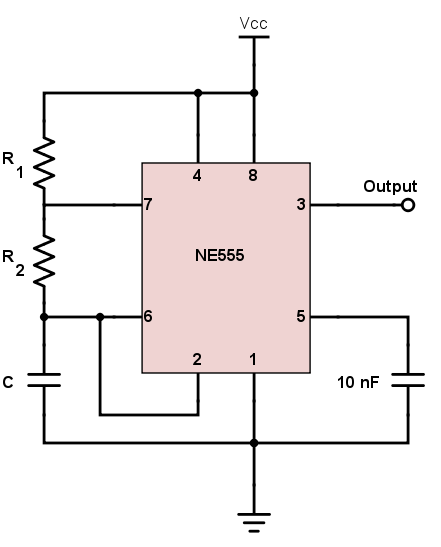
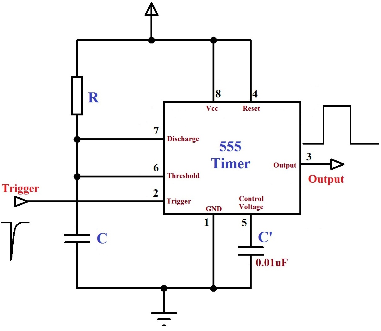
Nov 03, 2018 · 555 timer here, 555 timer runs in free running mode i.e. This article covers every basic aspect of 555 timer ic. May 24, 2020 · if you want to learn more about the 555 timer, the book timer, op amp, and optoelectronic circuits and projects book vol. You may already know that se/ne 555 is a timer ic introduced by signetics corporation in 1970's. The threshold voltage for the first ic 555, which is determined by the control voltage (modulating signal), is changed to utl (upper threshold level) and is given by. The control input is used in some of the applications, but most of the applications the control input is not used hence the control voltage is equal to +2/3 vcc. In other words, 555 timer is a circuit which may be connected as a stable or monostable multivibrator. 4th pin is connected to vcc to avoid sudden resets. Apr 07, 2021 · the schematic of the pulse position modulator using two 555 timer ic's is shown below. Between the positive supply voltage v cc and the ground gnd is a voltage divider consisting of three identical resistors, which create two reference voltages at 1 ⁄ 3 v cc and 2. In more simple words, 555 timer is a monolithic timing circuit, which can produce accurate timing pulses with 50% or 100% duty cycle. This tutorial provides sample circuits to set up a 555 timer in monostable, astable, and bistable modes as well as an in depth discussion of how the 555 timer works and how to choose components to use with it. Derivatives provide two (556) or four (558) timing circuits in one package.
The 555 timer ic is an integrated circuit (chip) used in a variety of timer, delay, pulse generation, and oscillator applications. This article covers every basic aspect of 555 timer ic. The internal block diagram and schematic of the 555 timer are highlighted with the same color across all three drawings to clarify how the chip is implemented: You can watch how each of the circuits in this tutorial work in this video: In more simple words, 555 timer is a monolithic timing circuit, which can produce accurate timing pulses with 50% or 100% duty cycle.
Monstable Multivibrator using 555 Timer from electrosome.com In more simple words, 555 timer is a monolithic timing circuit, which can produce accurate timing pulses with 50% or 100% duty cycle. Jul 24, 2019 · the working principle of the 555 timer is by considering the block diagram of the 555 timer ic. The threshold voltage for the first ic 555, which is determined by the control voltage (modulating signal), is changed to utl (upper threshold level) and is given by. The 555 timer ic is a very cheap, popular and useful precision timing device which can act as either a simple timer to generate single pulses or long time delays, or as a. In 2017, it was said over a billion 555 timers are pr. It was commercialized in 1972 by signetics. The first comparator has threshold input to pin 6 and control inputs for pin 5. The basic 555 timer gets its name from the fact that there are three internally connected 5kω resistors which it uses to generate the two comparators reference voltages.
Derivatives provide two (556) or four (558) timing circuits in one package.
Between the positive supply voltage v cc and the ground gnd is a voltage divider consisting of three identical resistors, which create two reference voltages at 1 ⁄ 3 v cc and 2. Apr 07, 2021 · the schematic of the pulse position modulator using two 555 timer ic's is shown below. In 2017, it was said over a billion 555 timers are pr. The first comparator has threshold input to pin 6 and control inputs for pin 5. Derivatives provide two (556) or four (558) timing circuits in one package. May 24, 2020 · if you want to learn more about the 555 timer, the book timer, op amp, and optoelectronic circuits and projects book vol. The threshold voltage for the first ic 555, which is determined by the control voltage (modulating signal), is changed to utl (upper threshold level) and is given by. This tutorial provides sample circuits to set up a 555 timer in monostable, astable, and bistable modes as well as an in depth discussion of how the 555 timer works and how to choose components to use with it. 555 timer is a digital monolithic integrated circuit (ic) which may be used as a clock generator. The internal block diagram and schematic of the 555 timer are highlighted with the same color across all three drawings to clarify how the chip is implemented: The 555 timer is a chip that can be us… The control input is used in some of the applications, but most of the applications the control input is not used hence the control voltage is equal to +2/3 vcc. You can watch how each of the circuits in this tutorial work in this video:
It was commercialized in 1972 by signetics. The basic 555 timer gets its name from the fact that there are three internally connected 5kω resistors which it uses to generate the two comparators reference voltages. This article covers every basic aspect of 555 timer ic. Between the positive supply voltage v cc and the ground gnd is a voltage divider consisting of three identical resistors, which create two reference voltages at 1 ⁄ 3 v cc and 2. The threshold voltage for the first ic 555, which is determined by the control voltage (modulating signal), is changed to utl (upper threshold level) and is given by.
555 Timer Monostable Circuit Triggered When Circuit is ... from i.stack.imgur.com In 2017, it was said over a billion 555 timers are pr. 555 timer is a digital monolithic integrated circuit (ic) which may be used as a clock generator. Utl = 2/3 v cc + v mod Jul 24, 2019 · the working principle of the 555 timer is by considering the block diagram of the 555 timer ic. The 555 timer ic is an integrated circuit (chip) used in a variety of timer, delay, pulse generation, and oscillator applications. It was commercialized in 1972 by signetics. Between the positive supply voltage v cc and the ground gnd is a voltage divider consisting of three identical resistors, which create two reference voltages at 1 ⁄ 3 v cc and 2. The 555 timer ic is a very cheap, popular and useful precision timing device which can act as either a simple timer to generate single pulses or long time delays, or as a.
The 555 timer ic is an integrated circuit (chip) used in a variety of timer, delay, pulse generation, and oscillator applications.
You may already know that se/ne 555 is a timer ic introduced by signetics corporation in 1970's. 1 by forrest mims is a great resource to have on your bench. The 555 timer is a chip that can be us… Derivatives provide two (556) or four (558) timing circuits in one package. The first comparator has threshold input to pin 6 and control inputs for pin 5. The 555 timer ic is a very cheap, popular and useful precision timing device which can act as either a simple timer to generate single pulses or long time delays, or as a. The basic 555 timer gets its name from the fact that there are three internally connected 5kω resistors which it uses to generate the two comparators reference voltages. In other words, 555 timer is a circuit which may be connected as a stable or monostable multivibrator. Jul 24, 2019 · the working principle of the 555 timer is by considering the block diagram of the 555 timer ic. Utl = 2/3 v cc + v mod In this article, we cover the following information about 555 timer ic. The threshold voltage for the first ic 555, which is determined by the control voltage (modulating signal), is changed to utl (upper threshold level) and is given by. 4th pin is connected to vcc to avoid sudden resets.
, is changed to utl (upper threshold level) and is given by.)